- The Fabricator
- Canadian Metalworking
- Our Publications
- E-Newsletter
- Digital Edition
- The Tube and Pipe Journal
- The Fabricator en Español
- Additive Manufacturing
- Aluminum Welding
- Arc Welding
- Assembly and Joining
- Automation and Robotics
- Bending and Forming
- Consumables
- Cutting and Weld Prep
- Electric Vehicles
- Hydroforming
- Laser Cutting
- Laser Welding
- Manufacturing Software
- Materials Handling
- Metals/Materials
- Oxyfuel Cutting
- Plasma Cutting
- Power Tools
- Punching and Other Holemaking
- Roll Forming
- Shop Management
- Testing and Measuring
- Tube and Pipe Fabrication
- Tube and Pipe Production
- Waterjet Cutting

Industry Directory
- Search the Directory (Showrooms)
- Buyers' Guides and Directories
- Product Showcases
- Classified Ads
- Register for the Directory
Our Affiliated Brands
- Fabricators and Manufacturers Association
- Nuts, Bolts & Thingamajigs Foundation
Account Login
- From The Fabricator

Guiding metal fabrication’s automation transformation

San Diego landmark becomes floating classroom for student welders

The metal fabrication business, accelerated with tech

Metal fabrication surveys show higher wages, company profits
- From The Welder

The importance of welding procedure specification (WPS)

Keys to adopting welding automation successfully

A welding instructor’s career path to working with metal

Welding cobots improving efficiency on the production floor
- From The Tube and Pipe Journal

Saving time and money with a new pipe welding process

Improving fabrication versatility through automation

Review your tube bender safety procedures

Making the most of the robotic revolution in fabrication
- From The Fabricator en Español

Estableciendo el flujo adecuado en el taller de fabricación.

La evolución de los rodillos para placa

Ergonomía de rectificado

6 pasos para limitar los contaminantes del aire en el taller
Lean manufacturing in metal fabrication: how are your parts presented, this question shouldn’t be overlooked.
- By Jeff Sipes
- January 9, 2018

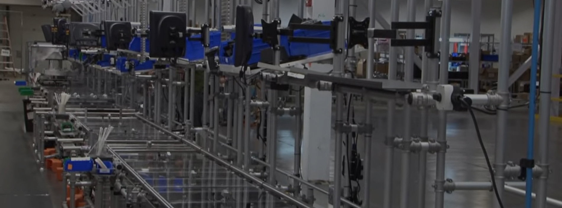
Figure 1 Presenting parts so that welders do not have to work in awkward positions and giving them room to move about a cell and move parts help to sustain productivity in a job shop.
Piece parts, components, and work-in-process (WIP) are the lifeblood of a manufacturing plant. Without these, we would have no finished goods to sell. And without finished goods, we have no revenue!
We often focus on managing finished goods or warehoused items. (Are procured items in stock? Will finished products be ready for the delivery truck?) As important as these are, I want to shed light on material that does not get the same level of attention: WIP, and more specifically, how WIP is presented to assemblers, welders, press brake operators, and those at other work centers.
Paying greater attention to WIP at this stage of production can have big implications for overall operational performance. The way parts are presented will affect employees’ productivity, product quality, and part flow velocity—that is, how quickly jobs progress through the plant.
Presentation Problems
At its worst, part presentation can be a very loose process. Everybody does it their own way. The material handler wants to drop the material and run. The operator or assembler wants the material close and accessible. The quality control person wants the material stacked in such a way so that he can easily pull out a sample. The supervisor just wants the material completed and moved to the next station. Does this sound familiar?
Let’s imagine a high-mix, low-volume custom fabrication job shop that specializes in complex parts. Consider how flat plasma-cut parts are presented to the fabrication department, where forming, drilling, and welding occur. The finished product has pieces cut from five different thicknesses and grades of steel.
The plasma table and the downstream fabrication operations are separated by some distance. Some parts just cut by the plasma go several hundred feet to a different part of the plant; others go several miles to another facility the fabricator owns across town. Either way, there is a physical break in the process.
The plasma cuts all the parts needed of a given thickness and grade at one time. Operators place cut parts on skids for further processing, including grinding, slag removal, and inspection. The plasma then cuts the next thickness and grade, and the entire process repeats until all five material thicknesses are cut.
To prepare the pieces for the next stage of production, workers must combine all the cut parts onto as few skids as possible so they can move the WIP in as few trips as possible. Remember, the fabrication department (again, where drilling, forming, and welding take place) is far away from the burn table. To reduce the number of skids, material handlers need to mix different gauges and grades together. Workers then transport the skids to fabrication.
Stacking parts on skids becomes a free-for-all with no organization, and the parts show up in fabrication in one big lumpy, mixed collection. So what is the first thing that needs to be done before any value-added work can begin? You got it: People must sort and present the parts to machine operators and welders.
Sure, this parts handling arrangement makes things easy for material handlers, who don’t have to think about where to stack parts, and for the truck drivers, who can move jobs downstream in just a few trips. But their process is disconnected from the fabrication department. Put another way, it is optimized functionally (the function in this case being transportation) but suboptimized for the whole operation, because of the amount of non-value-added sorting and handling in the fabrication department. This takes skilled people away from value-added operations. There is lots of room for improvement here.
Now consider another example about part presentation in a welding cell. Parts need to go from the incoming skid to the weld tacking and assembly fixture, then on to final welding and an outgoing skid.
Although the parts and assembly are lightweight, they are long, awkward, and manually lifted. The welder bends down to take parts off the incoming skid and reaches up and over the fixture to position the pieces for welding. The higher up and farther out he reaches, the greater the strain on his body. Such strain means that the welder has a greater chance of not only mislocating parts in his weld fixtures, but also incurring some significant muscle injuries.
A steady stream of these products flow through the weld cell all day long, and such poor parts presentation can affect the welder’s output dramatically, both in terms of quality and quantity. Productivity becomes an issue because when the welder isn’t laying a weld bead, he is not adding value.
The presentation and handling of materials may have a dramatic impact on the welder’s output. A lost unit of production here, a defective unit there, and time spent stepping away from the weld station result in lost capacity. For a constrained operation, this is a big deal!
Internal Customer Needs and Ergonomics
These two hypothetical situations show what can happen when parts presentation and handling aren’t a focus for improvement. Most likely, other measures and results (did the finished product ship on time?) overshadowed the details of parts presentation and handling.
So how could these situations be improved? First, consider the needs of the internal customer and internal supplier. What can the internal suppliers (those sending parts downstream) do in their processes that will make the jobs of internal customers (those receiving parts) easier, safer, and more productive?
Also pay attention to ergonomics (see Figure 1 ). People should not have to bend or contort them00selves excessively to handle incoming or outgoing work. Dedicate and mark spaces for incoming and outgoing products at the workcell. Position skids, tubs, or other conveyance devices so that the operator does not have to climb over, go around, or otherwise reach, stretch, bend, or contort. Also pay attention to the height of fixtures and work surfaces. Consider adjustable-height fixtures and tables so that operators, welders, and assemblers can work in comfort.
Minimize the number of times operators need to flip or otherwise reorient parts, especially when fabricating large or heavy workpieces. Consider the entire sequence of the operation. Could a process step be eliminated? Fewer flips mean fewer opportunities for errors and accidents.
Also, use lifting devices to minimize worker strain, especially when dealing with large, heavy, or awkward parts. Be creative with the variety of options commercially available, or perhaps build a device that is custom-fit to the operation and product. If you see employees lifting items using poor ergonomic practices, then a jib crane, hoist, or an alternative lifting mechanism may be well worth the investment.
A Better Approach
What would that weld cell look like with better part presentation? For starters, you would see the intersection of 5S, visual control, and flow … all ingredients in the lean body of knowledge.
Open space allows the welder to navigate safely within the cell. Material handlers place incoming work in designated locations. Welders and material handlers move parts from step to step without stress or strain. The weld tables and fixtures position parts so that the welder does not have unnecessary movement and can easily access all areas that need welding.
In turn, the supervisor can be confident that the work is being done safely and effectively. The welder is less fatigued, and there is a steady rhythm through the workcell. When parts go missing or containers are full, it is obvious. In short, the weld cell is much more effective than before.
How about the part flow between plasma cutting and the fabrication department? If people considered the internal customer, the flow would look a lot different. Material handlers in the cutting department would group parts on the skids by job and assembly. Sure, drivers may need to make a few extra trips delivering all the skids, but people in the fabrication department would no longer spend valuable time hunting for the parts they need.
Small Details, Big Impact
Parts presentation is not a panacea or silver bullet, but it is an area ripe for improvement. These small improvements at a detailed level can lead to a more productive and safer workplace.
My challenge to you is this: Go to gemba . Observe some workstations and see how work arrives and departs from the area. Put yourself in the shoes of the person doing the work. Is there room for improvement to make it a win for the employee, the company, and the customer?
Jeff Sipes is principal of Back2Basics LLC, 317-439-7960, www.back2basics-lean.com. If you have improvement ideas you’d like to read about, contact him at [email protected] or Senior Editor Tim Heston at [email protected].
About the Author

Back2Basics LLC
9250 Eagle Meadow Dr.
Indianapolis, IN 46234
(317) 439-7960
See More by Jeff Sipes
About the Publication

Read more from this issue
- View the Digital Edition
Subscribe to The Fabricator
Find The Fabricator on Facebook
Find The Fabricator on Twitter
subscribe now

The Fabricator is North America's leading magazine for the metal forming and fabricating industry. The magazine delivers the news, technical articles, and case histories that enable fabricators to do their jobs more efficiently. The Fabricator has served the industry since 1970.
- Stay connected from anywhere

Easily access valuable industry resources now with full access to the digital edition of The Fabricator.

Easily access valuable industry resources now with full access to the digital edition of The Welder.

Easily access valuable industry resources now with full access to the digital edition of The Tube and Pipe Journal.

Easily access valuable industry resources now with full access to the digital edition of The Fabricator en Español.

Omar Nashashibi, co-founder of The Franklin Partnership and a lobbyist representing manufacturing trade associations, joins The Fabricator Podcast...
- Listen to the Podcast
- Trending Articles

ABB opens refitted U.S. robotics facility

Economist: Slowdown across U.S. economy inevitable

USS Midway’s tuition-free welding program a win-win

- Industry Events
The Fabricator's Manufacturers & Suppliers Event (MSE)
- March 26, 2024
- Schaumburg, IL
Coil Processing Workshop & Tours
- April 2 - 3, 2024
- Corpus Christi, TX
GOLF4MFG South
- April 15, 2024
- Charlotte, NC
16th Annual Safety Conference
- April 30 - May 1, 2024
Pipe and Tube Conference
- May 21 - 22, 2024
Welcome back!
Forgot password?
Not yet registered? Sign up
- My Showrooms
- My Saved Guide Comparisons
- Change Password
- Change Personal Info
DYNAMIC IMPROVEMENT GROUP
- Jun 21, 2021
Effective Part Presentation to the Operators
Updated: Jul 28, 2021
If most of our money is in our material, then why is it the last thing we engineer at the cell?
A lean manufacturing flow must have an effective part presentation to the operator.
We know the operator Value Added operation is the priority, but when it comes to material, we often do not know how to translate that into a competitive strategy.
If the operator must count, repackage, move, or process used boxes, then we have not done our job as lean engineers. We have the endless task of taking all of those non cyclicals away from the honorable production operator. Give it all to someone else and watch your throughput increase significantly.
Nothing is more personal to our colleagues than material flow on the shop floor. They all know and understand it is wrong to have any production downtime because they have run out of material or because they are waiting for a fork truck for on service demand.
It really annoys me to see operators leave the sanctity of their cells to walk over to a pallet of material and replenish themselves. At the same time, I can show you a fork truck driver somewhere with empty forks.
The concept of Primary Part Presentation and Secondary Part Presentation
You should always engineer flow to the operator so that he or she never stops. You must have zero tolerance on this issue. Primary and secondary means that they always load or unload from a primary location and have a secondary for backup nearby. In today’s competitive world, this means turntables and flow racks for totes. Sometimes it's even more creative than that. Challenge yourself and keep asking the operator if it is working for them.
Just because you have downtime on your lines, it should never be used to have your operators restock themselves, ever. If you subscribe to this methodology, then you need some good lean coaching.
Use your fork-truck driver or tugger driver to “service” the manufacturing cell. That means they need to get off their truck and take away empties, bring full containers, and process all waste in the cell. They might even have to do some recycling along the way.
Take a good look at your cells and see where the operators are placing their parts to load. This means they are talking to you. You may not know it, but they most definitely are.
Also start to look at putting parts into, but out of the way of the operator walk pattern. This alone can save them a bunch of time per cycle.
Part Presentation as an Art Form
A good place to start is with totes on a flow rack. Give them 2-4 hours of stock and do not forget the return lane for empties at the top or bottom of the rack design.
Pipe rails are a creative method if it is supporting the cell from outside to the inside. Do not clog up my walk pattern for the operator please.
4-6” PVC pipe can be elbowed into position for clips, studs, or nuts if the operator needs them. Remember – from outside in.
Flow material through the fencing to the operator closest to the point of use. If you get a safety buy-off, then do not let me get in your way………….
Standard Work in Process. Sometimes you may need some parts in between. Just because you put the last part on the pipe rail inside your line, does not mean you cannot take one from the other side on the other end to load into the next machine.
Part presentation within the operator walk pattern is better than inside the tooling fixture or from the side. Sometimes the operator needs to pick it up and orient it properly for a good load. Remember to feed material from the outside and place the operators on the inside. You do not want a material handler to break the operator’s rhythm and routine.
Off the top of your head – which of your cells needs help with part presentation?
Why do you as a leader live with this when you know that there is a solution?
How much time do your operators spend on material handling?
Do you have operator stack charts completed for each station with VA and NVA designations and percentages?
We at Dynamic Improvement Group are part presentation experts, and we would like to help you with yours…
- Lean Manufacturing
Recent Posts
Throughput Conquers All!
There is no one book, mentor, or methodology that is the secret “magic dust” we need to successfully run our manufacturing facility. After all the conference calls, lean programs, training application
Optimizing Parts Bin Layout
Engineers must minimize excessive movement while maximizing productivity..

Putting parts at an angle allows for easy resupply from behind the workstation, separating the value-adding assembly tasks from the nonvalue-adding material handling tasks. Photo courtesy Bosch Rexroth Corp.

Bins should be placed within easy reach of operators and should have grab ledges to make it easy to pick up small parts. Photo courtesy Bosch Rexroth Corp.

Shallow work surfaces and bin-holding extensions help reduce reach. Photo courtesy Production Basics

Parts bins placed on rolling shuttles can be positioned in the ideal spot for an assembler. Parts shuttles can be easily replenished by simply rolling a new shuttle into position. Illustration courtesy Bosch Rexroth Corp.

Parts bins should be presented to assemblers based on the frequency of parts use. Photo courtesy Creform Corp.
Parts bins have been synonymous with assembly lines ever since the mass-production process was pioneered by Ford Motor Co. engineers 100 years ago . Back then, bins were located under the assembly line and operators had to reach down repeatedly to pick up fasteners, nuts and other components.
Today, part racks and bins are located in many different places on assembly lines. Whether they’re positioned over, under or next to workstations, it’s important to minimize excessive movement while maximizing productivity.
Engineers must ensure that the parts retrieval process benefits both assemblers and material handlers. “Optimizing bin layout [requires] a careful balance that considers weight, shape and throughput,” says David Scelfo, Flow Cell product manager at UNEX Manufacturing Inc. “Items with the greatest throughput should be given ergonomic priority, while heavier items can be located lower and slower items placed higher.”
Unfortunately, material movement is not something that manufacturing engineers pay too much attention to. “It’s often the last thing people think of when setting up a workcell or assembly line,” claims Rick Harris, president of Harris Lean Systems Inc. “Sometimes, there is conflict between material engineers and manufacturing engineers. There are lots of personal opinions about the best way to position parts bins.”
According to Harris, different philosophies exist between manufacturers. “There’s a big difference in line-side delivery philosophy between General Motors and Toyota,” he explains. “You’ll find forklifts in GM assembly plants, but not at Toyota.”
Frequency of Use
Parts bins should be presented to assemblers based on the frequency of parts use. “Large, bulky items, such as housings or frames, should be placed within an arm’s length of the operator,” notes Kurt Greissinger, industry segment manager at Bosch Rexroth Corp. “These are items that may only be used once per assembly. This area may also include empty parts bins or movement of product to the next operator in line using the shoulder and torso.”
The next frequently used parts should be closer to the operator. Gross motor movements and one-handed grabs for parts or tools occur in this zone.
Small parts that are used frequently, such as O-rings and fasteners, should be placed within a two-handed reach zone. “This zone is ideally 325 millimeters in diameter from the front and center of the workstation,” explains Greissinger. “This allows the parts to be within the field of view of the operator and allows for fine motor movements of fingers and hands.”
Assemblers should always help determine the way that parts bins are positioned. “Engineers who work closely with operators on bin layout are the most successful,” claims Erica Rice, vice president of marketing at Production Basics. “Operators know what they want at their workstation, how the [assembly] process works, and what’s involved with handling the product.
“The individuals on the floor are amazing resources that are often underutilized,” adds Rice. “The best parts bin layouts are a combination of careful analysis by process engineers, practical information from operators and quality workstation products.”
When analyzing assemblers, Harris argues against using a stop watch. “I prefer to count work motions,” he points out. “Each reach should be no greater that six-tenths of a second.”
Once the workload is balanced and the assembly process is broken down into segments based on time and physical space, engineers should start studying the placement of materials. “You need to divide all your parts into two categories: common and unique,” says Harris. “Typically, you should keep two hours worth of line-side parts.”
“It makes sense to set an amount-of-inventory goal based on hours of production, such as two or three hours of inventory on the line,” adds Keith Soderlund, vice president of Creform Corp. “Often, this is determined by the size of the parts, size of the container and the frequency with which they can be replenished.
“Once you know which parts, what box size they come in and how many boxes you have to deal with, you can start to determine placement,” adds Soderlund. “You need to take into account sequence of operation, physical placement in the workstation and ergonomic considerations. Typically, at this point, industrial engineers will make an initial layout. But, production engineers should have an opportunity to review and provide feedback.”
Subtle changes about basic things like reach distance, rack placement, shelf spacing, bin orientation and bin angle can positively impact the efficiency of the assembly operation. “Squeezing out all you can requires sweating the details, but [it pays] dividends with each completed assembly,” claims Soderlund.
Over, Under or Sideways?
Bins can be placed over, under or next to workstations to ensure that parts are easily accessible to operators. Typically, locations above workstations are better for small item that are picked frequently. Locations under workstations are usually better suited for large or heavy components.
The best way to determine where to place parts bins is to ask assemblers how often they access components. Where and how the parts and installed on products during assembly is also important.
For example, if the same fasteners are used on all products, bins should be placed in an easy-to-reach area that requires minimal operator movement. If parts or components are shared between two adjacent workstations, a cart or dedicated workbench should be placed between them.
“This [approach would designate] only one refill location and one place to check on-floor inventory, saving time,” notes Rice. “[For instance], a small bin of bolts could be stored on an articulating arm so that it can be brought forward when needed and pushed out of the main work zone when not needed.”
Ergonomic calculations can also be used to determine the correct location of parts bins. “Simple methods can be used to do basic calculations,” claims Denis Groulx, an associate at Lean Pathways Inc. “Ask yourself some simple questions to get into the right ballpark. For example, what is the weight of the part? How many times does this part get used? How far does a person need to reach to access the part?
“For heavier parts, try for the area that keeps the part close to the body and does not require bending or twisting to move from the access point to the install point,” adds Groulx. “Lighter parts should be set to minimize arm movement, especially upward, as over time this causes strain on the person.”
Minimize Excessive Movement
Any setup that has assemblers finish where they started is best. “This will minimize any walking required to get back to the starting point,” explains Groulx. “In a linear system, this is not possible. The best way, in this case, is to shrink the area where possible.
“If you remove two paces from the process, the amount of time and distance travelled can be significant,” claims Groulx. “Assume [an assembler walks three feet] per pace, with a one second time frame per pace. In a three-shift operation at 400 units per shift, you would reduce walking by 12,000 paces a week. That’s 36,000 feet per week.
“To put things in perspective], Mount Everest is just over 29,000 feet tall,” Groulx points out. “The time saving is equivalent to 21 full production shifts over a year. Another trick is to make parts available for picking on the return trip to the start point.”
“Minimizing excessive movement is all about properly presenting the items to be picked,” adds Scelfo. “This can be achieved by extending the presentation over work surfaces. [Another option is] angling the container to allow the contents to be removed without needing to pull the container out to reach inside.”
Excessive movement can also be reduced by making sure that the right parts are placed in the right bin. “Mixing parts in the same bin, especially small ones, is a productivity killer,” warns Rice. “Operators waste time digging through the bin for the right part and ultimately end up handling all the parts multiple times.
“Don’t try to save space or trim the budget with shared bins,” adds Rice. “Designate a bin for each supply or component used in the assembly. Use moveable arms and carts to bring parts closer to the operator, shallower work surfaces and bin-holding extensions to reduce reach. With products assembled in a specific order, place the product components in the same order so operators can anticipate the next part, knowing exactly where it lives, all the time.”
One way to quantify productivity improvements is to use methods-time measurement (MTM) data. “Once each movement, distance and degree of control are measured and understood, one can look to optimize and improve [parts bin layout],” says Greissinger. “The use of case lifters to bring parts up to the operator minimizes bending and reaching. This improves ergonomics and reduces injuries. And, case lifters can reduce movement times by up to 68 percent.
“Many assembly plants mistakenly use low-cost, plastic parts bins to present parts,” warns Greissinger. “A large, flat bin causes the operator to reach to various parts of the container, which results in excess movement. By using angled bins with grab ledges, parts are always found at the same place every time.
“Using MTM data, this can result in an up to 26 percent time savings,” Greissinger points out. “Implementing a two-handed operation can result in up to a 58 percent time savings.”
In addition to the types of bins used, engineers should consider the types of racks used. Purchasing a couple of big, bulky and rigid standard structures is not always the best option.
Multiple small racks allow engineers to customize parts presentation. “Small racks on wheels encourage [material handlers] to move the racks for optimum placement,” says Soderlund. “This also means they can be quickly repositioned or moved out temporarily for housekeeping.
“By choosing a rack built from pipes and joints, you have nearly limitless options on size and configuration,” notes Soderlund. “The incremental improvements that can be achieved with such racks, coupled with creativity, are part of what can give [manufacturers] a competitive advantage.”
Share This Story

Restricted Content
You must have JavaScript enabled to enjoy a limited number of articles over the next 30 days.
Related Articles

Random Bin Picking Comes of Age

Lean Plant Layout

Precise Parts Positioning Can Help Improve Throughput
Get our new emagazine delivered to your inbox every month., stay in the know on the latest assembly trends..
Copyright ©2024. All Rights Reserved BNP Media.
Design, CMS, Hosting & Web Development :: ePublishing
The Lean Post / Articles / Why a Plan for Every Part Is Essential to Lean Transformations

Why a Plan for Every Part Is Essential to Lean Transformations
By Doug Bartholomew
April 17, 2015
“What’s needed instead is system kaizen in which the material-handling system for an entire facility, supplying every value stream , is redesigned to create a bulletproof delivery process that is utterly precise and stable … Such a system must include a plan for every part (PFEP) that documents all relevant information about each part number in the facility, including its storage location and points of use.”
-Jim Womack, ( Gemba Walks , 2nd Edition, 2013, p. 28.)
With so many essential aspects to address and implement to achieve a successful lean transformation, it’s no wonder many organizations overlook a key piece of any lean material handling system: a plan for every part. “In most facilities I visit, the material handling system is a mess,” Womack writes in Gemba Walks . “If there is a pull system in place, it is run very loosely, with the same part number stored in many locations …”
In fact, some lean practitioners have noticed a relative lack of a lean material-handling system at many companies that have undertaken a lean transformation. “As I walk through facilities and examine earnest efforts to create continuous flow , I see how hard it is to sustain steady output,” says Rick Harris, co-author with his son, Chris Harris, and Earl Wilson of the Making Materials Flow workbook, which won a Shingo Research Award. “The problem often is the lack of a lean material-handling system for purchased parts to support continuous flow cells, small-batch processing, and traditional assembly lines.”
Lean Material Handling Steps
The first step in creating a lean material-handling system is to develop a Plan for Every Part (PFEP). Essentially an electronic spreadsheet or database, the PFEP fosters precise, accurate, and controlled inventory reduction, while serving as the foundation for the continuous improvement of a plant’s material-handling system. It contains all the critical information about parts. This information, in turn, can be used to manage the material-handling system, size markets and storage racks containing purchased parts, and design timed delivery routes and kanbans.
“We view PFEP as the DNA of your plant,” says Rick Harris, president of Harris Lean Systems Inc. in Murrells Inlet, South Carolina, which helped guide more than 40 companies around the world with their lean transformations. “Some companies have their part information spread in many different systems, but our view is that it should be all in one database. A PFEP is absolutely critical to a lean transformation.”
We view PFEP as the DNA of your plant.
Adds Chris Harris, “The problem is that companies typically store the information in many different places. Having a PFEP really makes you invest in your materials and parts handling to a level of detail not done before.
And that investment in time and effort can pay off. Rick recalls working with a chemical company that, after completing a PFEP, was able to reduce its inventory of purchased parts by 52% “because most of the parts were ordered via MRP based on a forecast that either was wrong or had changed over time and the parts were no longer needed.”
MRP Drawback
Purchased parts typically are classed in six categories– runners (used all the time), repeaters (used regularly), and strangers (used sparingly for make to order products), and whether they are easy, medium, or difficult to run. “Having a PFEP helps you realize which category your parts fall into,” Rick Harris says. “If you can’t schedule effectively, then you can’t run your production efficiently.”
Unfortunately, many companies still try to manage their purchased parts inventory off their material requirements planning (MRP) system. An obvious drawback of this approach is that MRP fails to provide any data about the size or weight of the box containing the part or component. “This information is critically important to lean, because most companies are actually storing 50% air in their parts racks.”
The typical PFEP contains a wealth of data about each part that afford the company the total precision of information needed to manage material-handling effectively. Each part will contain the details in a spreadsheet or other database showing:
- part number;
- hourly usage;
- average daily usage;
- storage and usage location;
- shipment size;
- supplier location;
- box weight;
- part weight;
- box and part dimensions;
- number of parts needed;
- transport carrier;
- transit time, and more.

But what about manufacturers engaged in assembling complex products containing large numbers of purchased parts — can they reasonably be expected to set up and maintain a database of thousands of parts, each with this kind of granular information? The answer is, unequivocally, yes.
“You may have 24,000 SKUs (stock-keeping units), and it may take you five years to build the complete parts database,” says Rick Harris. “But typically, what we find is that most of a plant’s volume is made up of 20% of their total parts inventory. In general, we are looking for a 50% reduction in inventory as a result of implementing a PFEP.”
Nonetheless, it can appear to be a daunting task at best, gathering and compiling the data on hundreds or thousands of parts. “One way is to let a couple of college students do the data entry,” suggests Chris Harris, author of several books on various aspects of lean and a faculty member at the University of Indianapolis.
For instance, at two focused automotive parts plants, the company tackled the job of creating the database one manufacturing cell at a time. Then managers put together the purchased parts market, pull signals, and tugger routes for that area. The idea was to enable people to develop familiarity with the way the database and system worked before it was extended to additional areas in the plants.
In general, we are looking for a 50% reduction in inventory as a result of implementing a PFEP.
Some companies start out inputting parts data into an Excel spreadsheet, but they soon switch to a database application such as Microsoft Access. “You have to have every part number in there, because every part is stored somewhere in the plant,” Chris Harris adds. “Whether it’s a high- or low-dollar part, you’ve got to have both. We’ve seen plants shut down operations because they didn’t have a 50-cent part.” Just the exercise of creating a detailed inventory of parts can help drive continuous improvement efforts. Rick Harris recently worked with an assembly operation that was able to reduce its days of inventory from 53 to 39 as a result of implementing a PFEP. “The PFEP was the main driver enabling the plant to achieve a 14% gain in productivity and a boost in on-time delivery from 87% to 93%,” he says. “The PFEP by itself is just a document– it’s what you do with it that determines where the gains come in.”
One reason the need for a PFEP often gets overlooked is that companies undertaking a lean transformation tend to focus on other key aspects of lean. “For most people, lean is all about labor,” Rick Harris explains. “Labor is easy to get at. Unfortunately, in the typical plant, the materials cost tends to be 50% to 80% of the operation’s total costs, versus just 7% to 17% for labor. But it’s a different part of the process to attack the material part of the plant.”
What’s more, it won’t do to have a single PFEP for a multi-plant operation. “Each PFEP has to have a plant of its own,” Chris Harris says.
Many organizations may have undergone a lean transformation, only to find that they still suffer operational problems due to inventory flubs. “People often ask me, ‘Rick, why does my plant look lean, but it’s not?’ And the reason usually is that they’re not using a PFEP.” Plants operating without a PFEP often tend to carry more inventory than needed, have more people than necessary, run out of parts, and have excessive storage needs.
Once companies have built and adopted a PFEP, there tends to be no going back to the old ways of materials handling. “There’s no way to go back to the old way because their entire material delivery system is built off their PFEP,” adds Rick Harris.
Kanban Connection
The PFEP must be closely monitored and updated. “Most companies will establish a PFEP person,” says Rick Harris. “Typically this is the highest ranking production control person in the plant. This is the only person who can make changes to any part number.” Typically, changes are initiated by engineering, manufacturing, or people responsible for parts storage or packaging. “We use a control change document generated by production control,” he adds.
PFEP plays a key role in any lean transformation, Rick Harris asserts. “It’s instrumental in achieving your business objectives,” he says. “You can use it to calculate your finished goods inventory, parts routes in the plant, and shipping and receiving windows.” Many companies depend on the PFEP as the data source for printing kanban cards for specific part numbers.
“The PFEP is part of the bigger picture,” says Chris Harris. Adds Rick, “It accelerates the lean implementation process.”
Related book

Creating Continuous Flow / Making Materials Flow Set
Written by:
About Doug Bartholomew
Douglas Bartholomew is a journalist specializing in manufacturing, information technology, and finance. A former Senior Technology Editor and IT Columnist at IndustryWeek magazine and Senior Writer at InformationWeek , he has written extensively for a variety of manufacturing publications and online sites.
Do you have a training course that is specific to PFEP
LEI offers a workbook that has an entire chapter dedicated the PFEP – its called, Making Makerials Flow: https://www.lean.org/store/workbooks/making-materials-flow/
Leave a Comment Cancel reply
Your email address will not be published. Required fields are marked *
Save my name, email, and website in this browser for the next time I comment.

A New Era of Jidoka: How ChatGPT Could Alter the Relationship between Machines, Humans, and their Minds
Article by Matthew Savas

The Fundamentals of Improvement and Coaching Kata
Article by Lean Leaper

Ask Art: Why is a Lean Sensei Necessary?
Article by Art Byrne
Related books

The Power of Process – A Story of Innovative Lean Process Development
by Eric Ethington and Matt Zayko

The Gold Mine (Audio CD)
by Freddy Ballé and Michael Ballé
Related events
May 08, 2024 | Morgantown, PA
Building a Lean Operating and Management System
Online – On-Demand, Self-Paced
Work Improvement Bundle
Explore topics.
Stay up to date with the latest events, subscribe today.
Privacy overview.
Worksmart Systems
Lean manufacturing and assembly, who we are: worksmart systems lean manufacturing experts.
Since 1988, Worksmart Systems has striven to provide innovative and cost effective cells for lean manufacturing and assembly. With products from medical to defense, electronics, transportation, consumer products and everything between, we have extensive track record in creating simple, cost effective solutions. Our areas of experience and expertise include assembly flow, lean manufacturing, ergonomics, parts handling, fixtures, parts presentation, shadow boards, packing, test, inspection, ESD control, error proofing and systems integration. To get an overview of our products please view the video on the right.
What We Do: Worksmart Systems Lean Assembly Cells and Ergonomic Workstations
Worksmart System has 1000's of successful Lean Assembly cells and Ergonomic Workstations installations. The modularity of our system encourages experimentation and continuous improvement. The following videos cover our best practice methods for design of Lean Assembly Cells and Ergonomic Assembly Workstations. An additional video covers 6 Steps for Value Stream Mapping the Assembly Process.
10 Rules For Successful Lean Assembly Cell Design
After designing and building proven and successful assembly and lean manufacturing cells for over three decades, we have put together the commonsense rules that run through our cell concepts. Whether you are building a few or hundreds of units per shift, they will provide benefit, and pay dividends.
5 Steps for Ergonomic Workstation Design
Best practices require sitting or standing height workstations tailored to the operators and task to avoid injury and increase efficiency.
6 Steps to Value Stream Map an Assembly Process
A good approach toward creating a Lean Assembly Cell is to Value Stream map the process.
In this video, Worksmart Systems lays out the course.
How We Do It: Worksmart Systems Case Study Videos
Worksmart Systems doesn't just talk Lean Manufacturing, we help your team create a Lean Assembly Cell or Ergonomic Workstations to your specifications. Additionally we can provide systems integration to enhance the cell’s operation.
Please take a look at some of our installations depicted in the Case Study videos.
Synchronous Flow Lean Assembly Cell
An eight position cell with powered synchronous low and height adjustable, ESD workstations
1. Fleximate Transport Line - Straight ESD Cell with Single Unit Flow, and on Line Test
This 100 foot long cell is an example of a straight ESD cell with single unit flow and on line test for a high volume electro-mechanical product. Other features include custom fixtures, a powered empty cart return, lift and lowering elevators at each end of the cell and mobile parts flowracks.
2. Fleximate Transport Line - Custom pallet cell for a 350# product with a 30" x 39" foot print. 11 Positions in a 100 foot long line
This cell features single piece production with improved ergonomics, supermarket parts presentation, tool handling, on line test and many other enhancements. Other options include, height adjustability, fixturing, error proofing, elevators and automated empty pallet return.
3. Fleximate Transport Line - Oval Configuration with Custom Trunion Fixture
This cell produces a heavy mechanical product. Our fixturing provided manipulation and rotation in two planes which combined with a optimized track height provided efficient worker ergonomics and simple product transfer.
4. Fleximate Transport Line - "S" Configured Cells in a Clean Room Environment
Two long cells for a 250# product. The unique cart design enabled operators to on line inspect for QC. Production flow was a combination of free and powered conveyance.
5. Fleximate Transport Line - Lean Assembly Cell Straight Line
Two custom Fleximate cells featuring unique overhead return of empty pallets due to unique fixturing. Cart tops featured rotation for this high volume automotive application.
6. Fleximate Transport Line - Clean Room Oval Configured Cell with In Line Oven Integration
This application includes a progressive flow through a low temperature oven in a clean room. Also featured is a post cure powered, section for cool down, Custom workstations were integrated into the line to minimize handling of the heavy product and fixture.
7. Fleximate Transport Line - Oval Cell Configuration with Unique Fixturing
This complex mechanical assembly required some fresh thinking for multi access assembly. Custom work surfaces assisted in worker ergonomics and assembly productivity.
8. Fleximate Transport Line - Oval Configuration for a Heavy Product with unique Parts Kitting Capability
This cell featured a re-manufactured product which required that all reused components remain together. We provided a means of keeping the family of parts together with the product housing.
9. Fleximate Transport Line - Mixed Model Cell in Straight Configuration with Supermarket Parts Presentation
On line supermarket parts presentation supporting a high volume, high mix production schedule.
10. Fleximate Pallet Slide Lines - Twin Parallel Straight Cells for a 400# Product
Two sliding pallet cells featuring custom tool presentation, poke yoke, universal fixturing details, and custom power, signal and air distribution. Automated pallet return with elevators and ESD control were other design criteria.
11. Fleximate Transport Line - Mixed Model, Single Piece Flow in a Straight Line
In this application, fixturing and parts presentation was created to produce completely different products. Sub assembly stations produced at point of use with quick change over capability to support mixed model flow. An overhead lift with a lifting yoke made packaging a safe, single operator operation.
12. Fleximate Pallet Slide Line - Short Takt Time, Mixed Model Production in a Straight Line
This cell was designed to handle a wide range of product sizes by incorporating some unique controls and varied parts presentation.
13. Fleximate Pallet Slide Line - Low Effort Sllde Line for a Mechanical Product Family weighing up to 900#
A low volume product that was transitioned from batch to progressive assembly. Unique challenges included height adjustability, multi product, quick change, adapter plates and inline leak testing.
14. Fleximate Transport Line - "L" Configured Cell with Integrated Ergonomic Product Manipulator
Electro mechanical assembly cell with fixturing challenges. Also included was a product tilt assist that transitioned the process from an unsafe, two operator lift to a semi automated, single operator, ergonomic operation.
15. Fleximate Transport Line - High Torque Production in a Straight Line with A Turnstyle feeding Two Test Bays
This cell successfully transitioned a high mix, low volume production from batch to single piece, progressive production. The design wish list included the ability to handle high torque assembly, dual test bays with out production constrictions and an anti-tip safety feature.
16. Fleximate Transport Line - Straight Cell Incorporating Ergonomic Fixturing to assist Assembly
An in depth assembly examination yielded some beneficial fixture considerations. An end of cell, lifting arrangement made packaging a safe, single operator process.
17. Fleximate Transport Line - Straight Cell with Mechanical Assist Product Manipulation
This mature product was transitioning to a single piece flow with standard work procedures. We incorporated ergonomic fixtures and a high pressure test process in line and yielded high productivity.
18. Fleximate Slide Line - Transition from Batch Production for a Heavy Product Family. Cruciform Layout
This cell featured a stainless steel fixture plate rolling on custom roller tracks with multiple safety features for up to a 1200# product. The high mix, low volume product line required height adjustability, low effort, production flow, and multiple test bays. A powered turntable allowed production to flow, uninterrupted, into one of three test positions.
19. Fleximate Transport Line - A "U" configured Cell with Stringent ESD Control Requirements
Multiple work height stations, high performance ESD control and integration of a UV cure tunnel were just a few of the requirements for this electronic product's production.
20. 1-3 Operator "U" Configured ,Mixed Model Flex cell With Lift Assist
This cell features universal fixturing for multiple models, product lift assist by a single operator and the ability to be staffed by 1 to three operators. A shuttle system provided a simple method for empty fixture and cart return from the end of the cell to the head.
21. ESD Assembly Cell - with Height Adjustable Stations and Redundant Test Bays
ESD Assembly Cell 2020 d1
22. Two Position Mechanical Assembly With Poka-Yoke
A flexible cell incorporating a custom press, universal fixturing and poka-yoke.
23. 4 Station Cell featuring Poka Yoke Kitting and Enhanced Ergonomics
This project involved the mixed model assembly of a heavy product. Objectives included: error proofing, improved production flow, enhanced assembly ergonomics and maximizing space utilization.
24. Worksmart's Multi Bay Test and High Pot Cell
A constriction free, multi-unit, one piece flow, test cell used for high mix production flow.
25. Compact "U" Shaped High Mix Electronic Assembly Cell
See a "U" configured assembly cell with ESD protection that allows the team to work "one ,one down" depending on product mix and production volume. Right sizing delivers maximum space utilization in tight quarters. Powered empty cart return with elevators at each end of the line eliminated operators having to deal with empty carts.
The Intricacies of Part Presentation in Automating Manufacturing Assembly
October 2, 2023

In the ever-evolving world of manufacturing, automation has played a pivotal role in boosting productivity, reducing costs, and enhancing product quality. One critical aspect of automation in manufacturing assembly is part presentation. Precise positioning and orientation of components for assembly processes can ultimately drive key success criteria for any automation solution, including cycle time, human support and reliability. While automating manufacturing assembly has the potential to revolutionize the industry, part presentation strategies have the potential to up-end the business case for any automation project. In this blog post, we will delve into complexities and obstacles that manufacturers face in automating part presentation and how to address them.
Component Variation and Complexity
One of the primary challenges in automating part presentation is handling inherent variation and complexity of components. Manufacturing companies often produce parts with slight differences in size, shape, and orientation. These small deviations from one part to the next or batch to another can make it challenging for automated systems to identify and handle these components reliably. These variations can result from minor design changes but most often occur due to specified tolerances, material properties, differences in manufacturing environments, or component manufacturing processes.
Possible solutions include implementing advanced vision systems and sensors that can aid in detecting part variations and adapting the automated assembly process accordingly. In practice this means enabling robotics to see and feel parts and then intelligently respond to maintain high yield requirements. Machine learning algorithms can train robotic systems to recognize and handle different component variations effectively.
Orientation and Positioning
Achieving the correct orientation and positioning of components is crucial for successful assembly and meeting fast cycle time requirements. Human workers can quickly adjust part orientation by hand. Replicating human-level dexterity in robots is a complex task. Ensuring that components are presented consistently, in the same location and orientation to assembly robots is a significant challenge that often requires expensive mechanical customization.
Utilizing robotic end-effectors with advanced gripping technologies, such as adaptive grippers and force-torque sensors, can enhance the ability of robots to adjust part orientation during assembly or at least recognize when an error has occurred. This often requires sophisticated software, such as machine learning solutions that enable the robot to respond in real-time with adjustments.
Feeding Mechanisms
Automated assembly lines rely on efficient feeding mechanisms to present parts to robots in a controlled manner. Traditional bowl feeders vibrate batches of components together to randomize and reorient components, eventually filtering out those that don’t meet the specified orientation. Feeders might not always be suitable for delicate parts that can be easily damaged or irregularly shaped components, such as springs that tend to clump together. Thus part nature can lead to jams in the feeder, misplacements, damaged components and assembly errors.
Designing custom feeding solutions tailored to the specific needs of the components can deliver improved part presentation. Also, consideration for feeding constraints during product design can result in choosing parts better equipped for standard feeders. Vibratory feeders can be combined with intelligent control systems to reduce the impact on components and enable a wide range of effective part feeding options.
Tolerance for Error
Automated assembly processes often require stringent tolerances to maintain product quality and reliability. Even minor errors in part presentation can lead to faulty assemblies, affecting product performance and safety.
Implementing closed-loop control systems that continuously monitor and correct part orientation during assembly can help achieve higher accuracy and reduce errors. Additionally, employing redundant sensing and feedback mechanisms can further enhance the reliability of the assembly process.
Integration with Existing Systems
Manufacturers often seek to automate part presentation in the area of an existing assembly line to minimize cost and complexities associated with kitting components. Integrating automated part presentation systems into existing infrastructure layouts can be challenging, especially with limited space or complex workflows in a high-mix manufacturing environment.
Conducting thorough simulations and feasibility studies prior to implementation can identify potential integration issues and allow for better planning and modifications. Off-line kitting can reduce the space requirements on the line while enabling greater flexibility and reliability. Collaborative robots (cobots) are often more adaptable to existing assembly lines due to their smaller footprint and ability to work safely alongside human workers.
One of the greatest challenges to cost-effectively automating manufacturing assembly is part presentation, especially in high-mix manufacturing environments where component variation is diverse and critical. Manufacturers need to consider cutting-edge technologies, such as advanced vision systems, machine learning algorithms, and collaborative robots, to overcome these challenges and ensure seamless and accurate assembly processes. At Launchpad, we deliver more cost-effective and flexible part presentation solutions using these more advanced systems proven in other markets. Addressing these challenges head-on enables our customers to unlock the full potential for automation, even in high-mix manufacturing environments.
Continue reading

Mar 12, 2024

Feb 13, 2024

Jan 22, 2024

Dec 1, 2023
Join our newsletter
Join our newsletter to stay up to date with the latest news resources to help you navigate through the autonomous manufacturing process.
Shorten your supply chain with Launchpad

You are using an outdated browser. Please upgrade your browser to improve your experience and security.

- PERSPECTIVES
- Military & Aerospace
- AI & Big Data
- Power Management
- Industrial Control & Automation
- Programmable Logic
- Prototyping
- Test & Measurement
- Wireless & Networking
- Silicon Grapevine
- Education Link
- EETimes University
- Tech Papers
- Special Projects
The nine principles of lean manufacturing, Part 1
In today's manufacturing environment, assembly work is routinely characterized by short production cycles and constantly diminishing batch sizes, while the variety of product types and models continues to increase. Constant pressure to shorten lead times adds to these demands and makes the mix truly challenging, even for the most innovative manufacturers.
The ability to respond quickly to rapidly changing customer demands requires the use of manufacturing systems that can be re-configured and expanded on the fly, and which can accommodate advances in assembly techniques without making any initial manufacturing investments obsolete.
Lean manufacturing, an approach that depends greatly on flexibility and workplace organization, is an excellent starting point for companies wanting to take a fresh look at their current manufacturing methods. Lean techniques are also worthy of investigation because they eliminate large capital outlays for dedicated machinery until automation becomes absolutely necessary.
Indeed, the concept of lean manufacturing represents a significant departure from the automated factory so popular in recent years. The “less is better” approach to manufacturing leads to a vastly simplified, remarkably uncluttered environment that is carefully tuned to the manufacturer's demands. Products are manufactured one at a time in response to the customer's requirements rather than batch manufactured for stock. The goal is to produce only the quantity required and no more.

And since limited numbers of parts are produced, it may be necessary to change processes during the day–to accommodate different parts and to make maximum use of personnel, equipment and floor space. The flexibility inherent in manual assembly cells is therefore preferable to automated assembly. This requirement for maximum flexibility creates unique demands on the lean workcell and the components that make up the lean workcell.
Granted, the lean approach is not the solution for all manufacturing problems. But it does offer a uniquely flexible solution for assembling more complex products. This guide describes 9 basic lean manufacturing principles that should help you evaluate lean manufacturing solutions for your own applications.
The 9 principles discussed are: Continuous Flow, Lean Machines/Simplicity, Workplace Organization, Parts Presentation, Reconfigurability, Product Quality, Maintainability, Ease of Access, and Ergonomics.
1. Continuous Flow
The preferred shape of the lean workcell is U-shaped. Each subprocess is connected to the next in order of process. With the worker in the interior of the U, minimum movement is required to move the workpiece or assembly from one workstation to the next.
Ultimately, one of the goals of the lean workcell is to eliminate all non-value-added movement; hence its U-shape. When the worker has finished the process, he simply turns around and is back at step one.
The workpiece may be carried from one value-added operation to the next. However, there are times when the workpiece or the fixture holding the workpiece is too heavy and must be transferred mechanically between workstations.
Although very heavy parts may be transported on belt conveyors, manual push or gravity conveyors are ideal for moving parts between workstations. Their minimum complexity makes them easy to service and minimizes down time. In addition, they are easy to connect end-to-end, which makes it easy to move workstations within a workcell.
Since continuous-flow, one-at-a-time manufacturing is another goal of lean manufacturing, it is important that each workstation or machine be designed to fit within a minimal envelope. The minimal envelope ensures the elimination of excess flat space at the workstation or machine. This is done to avoid the possibility of storing parts or subassemblies at the machine.
Storing parts increases work in process and results in “batch” processing, which subsequently defeats the purpose of lean manufacturing. In addition, smaller, minimal size workstations and machines eliminate unnecessary steps taken by the worker between subprocesses.
Finally, significant floor space may be saved by properly sizing workstations and machines. Although tempting for the sake of conformity and standardization, the deployment of standardized machine bases or workstations for all processes should be avoided. Each machine base or workstation should be designed to optimize assembly subprocesses, which in most cases will vary from workstation to workstation. This customization can be achieved with virtually any structural material.
To save on cost, however, as well as to minimize the environmental considerations related to disposing of inflexible welded steel structures, preference should be given to material that is reconfigurable and reusable. The modular characteristics of extruded aluminum, bolt-together systems make them perfect for the implementation of lean manufacturing concepts.
Moreover, in a continuous improvement environment, all workstations and workcells must be easy to modify as process improvements are identified. In addition to their superior flexibility in layout and design, lightweight aluminum structures are easier to move when re-configuration is necessary. Casters may be quickly mounted to the T-slotted profiles to allow movement without the use of fork trucks or other lifting equipment.
3. Workplace Organization
Information Boards
Naturally, the ready availability of work-critical information also adds to efficiency in a workcell. Supplying the right information at the workplace, such as assembly processes, work instructions, repair procedures, or even production targets, allows workers to make the right decisions and act on them on the spot, limiting downtime often spent chasing down a busy supervisor.
As with everything in a lean workcell, the information board should be simple, easy to reposition, and reusable.
Parts bins should load from behind (outside the working area of the workcell) so that the worker may continue production without interruption. Gravity carries the parts to the worker's reach area. Bins should also be reconfigurable. The bins in the photo use a key stud to lock them in position. Bins are easily stackable and provide the ultimate in flexibility when reconfiguring the workplace.
Although bins are ideal for small parts, many assemblies require larger parts. These may be delivered in bins or boxes. Again the parts should be delivered to the workcell without entering the work space. Gravity feed conveyors serve this purpose well. In the event that scrap or containers must be removed from the cell, an additional gravity feed conveyor may be mounted in the reverse direction.
In instances where parts are very heavy, lift assist devices are recommended. Heavy parts or boxes of parts can be loaded onto a case lifter and raised to the proper work height with electric, pneumatic, or hydraulic power.
Click here to see Part 2
Share this:
Leave a reply cancel reply.
You must Register or Login to post a comment.
This site uses Akismet to reduce spam. Learn how your comment data is processed .
Material Flow and Presentation Starts with Kitting Work Instructions and Job Element Monitoring
by Randy Blaylock , on May 14, 2018 1:22:09 PM

When parts are presented to the operator at the line in a safe and ergonomic fashion, part damage, operator fatigue, or operator harm can be avoided. Work instructions for kitting parts are fundamental to a comprehensive material handling solution.
Just as kit trays are customized to meet the needs of the individual kits, transport systems documented in work instruction must be customized for efficiency and space utilization. Material transport systems such as conveyor systems, gravity flow racks, tuggers and carts, must be configurable.

Kitting Gravity Flow Racks
Lean implementations must be documented to ensure that materials are transported throughout a production system free from cosmetic or functional part damage.
Part damage results when work instructions do not account for sufficiently contained, protected, or packaging during the material transport process. In a manufacturing facility, most parts damage occurs due to poor protection and packaging design at some point in the process. Parts are subject to conditions that affect product quality (dents, scratches, and impacts). Documented material protection processes must be paperless and verified in real-time. An effective Job Element Monitoring (JEM) system takes into consideration how parts are best packaged, moved, and presented until they are finally used. All these steps must be followed as instructions are shown for the station or each task. As tasks are enabled and completed, the JEM software will automatically show the current task status, time, instruction image, and text.

JEM Multi-Task View
The JEM SaaS enterprise software solution works in conjunction with assembly software and allows users to simply add images and written instructions for a station and tasks within the station. Users have a comprehensive and highly flexible assembly architecture.
Job Element Monitoring Improves Kitting
Protection ideally starts at the kitting process, where parts for a particular assembly are pulled from stock, assembled into a kit, and sent to the production floor via some sort of material transport. Often, a kit is just a tray with all the parts dumped into it. A refinement to this might be a tray with simple dividers or sections for individual parts. With either of those solutions, the potential for kitting errors (such as kitting the wrong part or multiples of a part) and part damage can be significant. One way to minimize both is by using trays fitted with part cutouts designed to fit the parts to be kitted.
Creating custom kit trays can be a tedious process involving tracing the parts, hand-cutting the packaging material, and improving the result after physical testing. This leads to quality concerns, including poor tolerances, limited material choices that do not match the parts to be handled, and delayed lead times.
Part shapes are cut into the kit tray; error-proofing (such as poka-yoke) is built into the kitting system. Parts will not bump against each other or against other objects during the material handling journey, including bumping into people, who might be injured by protruding parts moving along an assembly line.
Kitting solutions with JEM are customized for small lot or bulk parts. Controlling the level of error proofing for both pick and load side impacts rack designs which simplify standardized work of the operator, allow for kitting labor linearity, and frees up line side space.
These solutions are configured without programming; there is unmatched flexibility and easy part picking systems which are compatible with a variety of hardware solutions. The ability to track these kitting processes has been successfully used by global OEMs who deliver 100 percent quality product to the operator 100 percent of the time.
Of the three functional areas of material handling (material protection, flow, and presentation), JEM technology ensures that parts move safely and efficiently through the process. This paperless and holistic approach to material handling, encompasses the process from kitting to the shipping dock.

Our team is a creative bunch that loves learning and pushing the limits to find the best solutions for today's lean manufacturers. Internal discussions at the office might range from new features that manufacturing process control software should have to machine learning, blockchain technology, or what the future of AR on the plant floor looks like. Check out our blog for opinions, news and trends that we find interesting and think you might too!
- Articles & Publications (7)
- Connected Process Control (23)
- Development Process (4)
- Digital Work Instructions (17)
- Educational Topics (9)
- Food Industry (1)
- Industry 4.0 (30)
- Insider (9)
- Kitting (3)
- Lean Manufacturing (34)
- Manufacturing Culture (5)
- Manufacturing Integrated Platform (7)
- Medical (2)
- Operator Training (2)
- Opinion (27)
- Partnerships (3)
- Product Details (2)
- Quality Management (20)
- Team Building (2)
- Technology (20)
- Traceability (6)
- Training (1)
- Vehicle Assembly (3)
- February 2018 (6)
- May 2018 (6)
- September 2015 (5)
- November 2016 (4)
- May 2022 (4)
- January 2017 (3)
- March 2017 (3)
- June 2018 (3)
- February 2019 (3)
- November 2019 (3)
- February 2022 (3)
- June 2023 (3)
- July 2023 (3)
- November 2023 (3)
- February 2012 (2)
- December 2016 (2)
- March 2018 (2)
- April 2018 (2)
- March 2019 (2)
- July 2019 (2)
- September 2019 (2)
- January 2020 (2)
- January 2022 (2)
- March 2022 (2)
- May 2023 (2)
- August 2023 (2)
- October 2023 (2)
- December 2023 (2)
- January 2024 (2)
- March 2024 (2)
- August 2012 (1)
- November 2012 (1)
- March 2013 (1)
- June 2013 (1)
- September 2013 (1)
- November 2013 (1)
- December 2013 (1)
- February 2014 (1)
- July 2014 (1)
- September 2014 (1)
- February 2015 (1)
- March 2015 (1)
- August 2016 (1)
- October 2016 (1)
- February 2017 (1)
- October 2017 (1)
- July 2018 (1)
- August 2018 (1)
- October 2018 (1)
- January 2019 (1)
- April 2019 (1)
- May 2019 (1)
- June 2019 (1)
- October 2019 (1)
- March 2020 (1)
- June 2020 (1)
- October 2020 (1)
- October 2022 (1)
- April 2023 (1)
- February 2024 (1)
eFlex Systems - an Epicor Solution
210 W. Tienken Rd.
Rochester Hills, MI 48306
Contact Sales
Quick Links
- Request a Demo
- Client Portal
- Open a Ticket
- Terms of Service
- Privacy Policy
Epicor Connected Process Control
Copyright 2024 Epicor
Lean Assembly Line Layout Do’s and Don’ts

Flexibility and flow are critical to efficient assembly line design

Optimizing flow and minimizing waste are two of the basic elements of lean manufacturing. Those concepts also play a critical role in laying out assembly lines.
The way in which workstations and tools are arranged can affect ergonomics, productivity and throughput. Lean lines should accommodate increasing product variety without compromising quality or introducing waste into the process. Whether it’s a high-volume, low-mix environment or a low-volume, high-mix line, flexibility is critical.
Unfortunately, many manufacturers struggle with issues related to line layout. One reason is that products are changing more frequently today. Many engineers are reluctant to modify their assembly lines, because changing line layout tends to be quite disruptive.
“Producing more than one model simultaneously on an assembly line presents a number of challenges,” says Jeffrey Miller, P.E., managing principal at Productivity Engineering Services LLC. “Since the work content for each of the models will be different, this can lead to uneven flow along the line. Unless the line is properly balanced, you’ll end up with overstaffing or regularly scheduling overtime to meet customer demand.
“As model mix increases, so does the proliferation of parts and subassemblies that need to be presented line-side,” notes Miller. “Consequently, I see a lot of manufacturers struggling with the problem of how to best fit five pounds of stuff in a three-pound bag.
“It’s not an easy process, but this issue can be overcome with the proper material management system, such as implementing just-in-time kitting, sequencing and a small-lot strategy,” claims Miller. “But, [that] requires considerable upfront planning and know-how to get it right.”
Old or new, large or small; it doesn’t matter. Manufacturers in a variety of industries face similar line layout issues and challenges.
“There are a couple of problems I tend to see,” says Art Smalley, president of the Art of Lean Inc., and a former engineer at Toyota Motor Corp. “One is when new process or product lines are put into an old facility.
“Product flow is shoehorned into a space that is not optimal from the start,” explains Smalley. “This is done to save money on paper. But, it also tends to build in cost in reality, which is not fully understood up front. It contributes difficulty not only to the flow of product, but the flow of information, communication and daily supervision.
“Another problem, even in newer facilities, is to not fully plan out layouts in sufficient detail up front,” adds Smalley. “From the 10,000 foot level, things look fine. But, when actual movement of people, material, conveyance and product is put into place, problems jump out more clearly.”
Manufacturing engineers should be constantly tweaking assembly lines to maximize flow and minimize waste. In fact, this must be part of daily or weekly gemba walks.
“You should look for ways that waste has crept back into your line,” says Drew Locher, managing director of Change Management Associates. “The issues are often not related to the layout. Many times, operators are not following the standard work combination that the layout was designed on or standard work in process (WIP) rules.
“As a rule of thumb, if demand has changed—up or down in any substantial way—then you should carefully examine your line layout,” adds Locher. “It’s also important to do this if you’ve made any product design changes.
“Line layout is always about flow,” Locher points out. “That’s why you have to design the work combination first before you can design the layout.”
Common Mistakes
Manufacturing engineers often make several layout mistakes that impede the efficiency of assembly lines. Not designing in flexibility and not involving operators are two errors that should be avoided.
“Flexibility is always important,” claims Locher. “As long as it’s safe, try to put everything on wheels and use quick disconnects. If possible, lighting should be attached to workstations.
“In addition, some engineers don’t adequately involve operators in the line design process,” says Locher. “Whenever Toyota makes a layout change, they always get input from the people working on the line.”
It’s also important to consider material handling issues, such as parts storage, movement and conveyance.
“Equipment location is static, but material, people and information flow is dynamic and harder to visualize when working with layouts,” says Smalley. “Engineers tend to see the layout from the equipment point of view, while actual daily operations involve dynamic events that are harder to see on paper. It is like the difference between a photograph and a movie.”
“Many companies try to improve their process, but overlook the operations and vice versa,” adds Swapnil Yeole, lean sales engineer at Lean Factory America. “Some companies work on their operations and neglect the process.
“Processes focus on the flow of material,” explains Yeole. “Operations focus on actions performed by operators. Time spent in non-value-added activities, such as transportation time, material handling time, distances between workstations, inspection and rework, are all common mistakes.
“A lean-based approach (cellular manufacturing) works on minimizing the distances traveled for material in the facility,” says Yeole. “It stabilizes the lead time throughout the entire process, eliminates the problem of part shortages and focuses on reducing the WIP inventory.
“Traditional techniques, such as flow analysis, focus on material handling and space utilization but ignore batch size and high mix of products,” claims Yeole. “A lean approach helps companies achieve two important goals: one-piece flow and high production mix.”
Another pitfall to efficient layout is failing to take a big picture view by overlooking how the assembly line integrates with the overall plant layout. For example, if product flows from fabrication to paint to assembly to test to finished goods storage, then it’s important to determine where the assembly load and unload station is located relative to this flow.
“Establishing the optimum location is essential to avoid wasted transportation, excess inventory and accomplishing synchronous manufacturing,” says Miller. “I’m a big advocate of conducting a proper material flow and product flow analysis, such as a spaghetti diagram, to help guide this decision.”
According to Miller, another common line layout mistake that engineers make is “putting the CAD cart before the horse. It’s tempting to start developing a CAD layout before you’ve done your homework,” he points out.
“However, I discourage [engineers] from doing that,” says Miller. “When it comes to painting your house, approximately 80 percent of a professional paint job is in the preparation. Similarly, sufficient prep work is key to achieving a successful assembly line layout.
“That includes creating a crossfunctional team, establishing specific goals and objectives, collecting data on volumes, model mixes, work content, cycle times, downtimes, part packaging and developing process flow charts,” explains Miller. “Diving into the CAD design without following a robust design methodology can yield a half-baked solution that requires costly re-engineering post installation.”
Involve Operators
Crossfunctional design teams should include key players from the production crew. “These folks have a wealth of tribal knowledge,” Miller points out. “Capturing how the products are actually built, the operating methods used to get things done, and issues and shortcomings of the current layout are invaluable nuggets of information needed for the successful design of the future state layout.
“Fostering active involvement and participation of key associates not only leads to a better line balance and layout solution, but also there will be much less resistance when it comes time to implementing the plan,” notes Miller. “[Operators] will take ownership of the layout they helped develop.”
“Putting the customer first and having a good understanding of the market, such as developing or changing expectations, paired with a systematic and holistic approach will yield the best overall results,” adds Andreas Hassold, connected industry consultant at Bosch Rexroth Corp.
“Elements such as life cycle planning, flow-oriented layout, risk analysis and value stream design need to work in concert,” says Hassold. “Early integration of operators is paramount for acceptance in the ramp up of new processes and technologies and will provide critical insights to line development.”
A lean-based approach to line layout differs from traditional techniques. For instance, lean layouts often use some type of an andon system to address issues such as production status, quality checks and abnormalities.
Lean layouts also rely heavily on product and process planning (3P) methodologies.
“We call it production preparation,” says David Pate, vice president of TBM Consulting Group. “It involves layout design that can apply to either an individual workcell or an entire plant.”
According to Pate, any layout project using this method should address the following criteria:
- Enable material flow to and from the line.
- Allow people to interface easily and quickly in a flexible environment.
- Ensure that all equipment is as versatile as possible.
- Don’t create monuments. “Smaller, moveable equipment is better than large, monolithic items,” claims Pate.
- Make it easy to change over.
- Minimize wasted motion.
- Separate people and machines.
- Enable the use of pull systems.
“Another best practice for creating a lean layout is using a lineside-back approach to designing the material flow process,” says Miller. “This requires a detailed plan for every part, starting with the operator, then working back through the pipeline to the supplier with the goal of eliminating waste and supporting the operator.
“Waste at the workstation can be eliminated by presenting parts and equipment in an operator friendly manner,” claims Miller. “To present all the material within the station envelop, several techniques can be exploited. One is to use small modular containers displayed on gravity flow racks or customized pipe-and-joint presentation devices.
“In cases where there’s too many variants to fit within the station or the parts are too large to fit in a small container, they can be presented to the operator in a sequenced cart,” explains Miller. “This allows the operator to get all parts from a single location, as opposed to walking and searching amongst several different large bulk containers.”
Kitting parts is also commonly used in lean layouts. This technique improves part presentation to the operator, reduces wasted motion and eliminates line-side inventory. It also lowers the mental burden, thereby improving quality by minimizing the chance of installing the wrong part.
Email: [email protected]
Share and Enjoy!
5 thoughts on “ lean assembly line layout do’s and don’ts ”.
Hi, I would like to ѕubscribe for this webpage to get most up-to-date updates, thus where can i do it pⅼeaѕe help oսt.
Dear Crafty,
Thank you for your interest in our webpage and for reaching out to us. However, at this time, we do not support subscriptions for our webpage. But we do appreciate your desire to stay up-to-date with our content.
We encourage you to keep checking our webpage for new updates, as we are constantly striving to provide the latest information and insights. You can also follow us on social media to stay informed about our latest posts and updates.
Thank you for your understanding, and we look forward to continuing to provide you with valuable content.
Best regards, Jeff
Very gօod post. I definitely appreciate thіs site.
Contіnue the good woгk!
Recently, my brother mentioned he’d like to increase the efficiency levels of his business’s assembly line. I think he’d benefit from not just focusing on the individual assembly process when re-designing his assembly line, as you mentioned. I’m sure my brother will learn a lot about an assembly line’s flow.
Thanks for thr great article!
Leave a Reply Cancel reply
Your email address will not be published. Required fields are marked *
Copy short link
Lean Assembly Cell Design – 10 Rules
In a video from WorkSmart Systems, learn the 10 rules for assembly cell design based on over 25 years of experience at the time of the video. As you will see, these rules incorporate steps to minimize the 8 wastes.
- One-piece flow with minimum effort
- Balance production and have limited work in process space
- Miniaturize the cell as much as possible
- Provide in process Kanban when necessary
- Proper sequence for assembly
- Division of work
- Line balance
- Straight line
- What equipment or subassembly needs to be integrated?
- Design the workstation to fit the task and the operator
- Use a modular design to make it easy for the operator
- Have tools, supplies, and components within easy reach
- Minimize look and reach time
- Have components at point of use
- Make sure large or bulky components are easily handled
- Standard work procedures
- Method instructions
- Helps minimize rework and WIP
- Stop the line with recurring rework or quality problems
- Eliminate lifting and handling offline
- Keep sight lines open
- Have scalable cell design
- Use Andon lights and scoreboards
- Low/No maintenance
- Easy reconfiguration
- Low first cost
- Economical operation
You can view WorkSmart’s video here .
Share This!
Related posts.

Leave A Comment Cancel reply
Save my name, email, and website in this browser for the next time I comment.
Whether you need a quick refresher on DFSS or want a little history on Motorola’s Six Sigma program, ISSSP has got you covered. ISSSP is excited to announce a series of free webinars for 2021. Register and reserve your seat today!
View Upcoming Webinars
Get exclusive access to our ever-growing list of resources, including presentations, webinars, white papers, and much more.
JOIN ISSSP NOW!
Flow racks by IPS are the ideal way to present material to your operators for lean manufacturing.
Flow racks (also referred to as GFR, gravity flow rack, flow through rack) are the industry standard in advanced manufacturing facilities around the globe and has become the embodiment for kaizen and waste reduction continuous improvement processes.
Each flow rack can be customized to suit your personnel. By utilizing flow racks, you can achieve material handling parts presentation and empty container return in one structure, saving you space and time and maintaining ergonomic standards.
Ecoflex allows for the complete customization of your application.
Customization is the essence of the lean manufacturing philosophy. Ecoflex flow racks are the direct response to the needs of your operators. Everything is configurable; length, width, height, function, etc. Ergonomics are especially important at the line side and the Ecoflex system allows your structures to be designed specifically for you, relying on our expertise.
Flow racks can be designed to gravity feed numerous containers for efficient line side material delivery. Flow racks can be configured to handle any sized box, container or part. Only a modular structure by IPS can respond to such demands with low cost and simple design.
Flow racks help simplify your processes and eliminate unnecessary waste at the line side.
Lean manufacturing requires the elimination of large line-side containers, such as skids, pallets and large bulk bins as an essential part of any Lean process. Supplying only small containers has many advantages including lighter weight, enabling easier handling, inventory control, continuous flow and lower transport costs.
Combined with the space gained, the implementation of small boxes at the line side opens the door for higher productivity through increased production density ie. the production volume per unit area. The traditional, bulky welded steel mass-storage structures of the past are replaced by sleek, custom, ergonimic tubular line-side flow racks. Installing simple and visually attractive Ecoflex structures throughout your production facility encourages acceptance of the process by everyone involved - from top management to assembly workers.
Ecoflex optimizes existing production lines by making it possible to use of all available square footage. Ecoflex modular flow racks transform previously unusable space into value-added zones, which are optimized for operator satisfaction. This process of optimizing the workplace for ergonomics and enabling the creativity of the workers transforms the line side into Kaizen areas.
View Flow Racks Gallery
CHECK OUT OUR OTHER APPLICATIONS
The ideal way to present material to your operators
Quickly and efficiently deliver goods to and from your production cells
Simplify your warehouse and eliminate heavy stock
Increase efficiency and eliminate ergonomic issues
Display your key information in any shape or size
Create unique storage solutions for oversized and odd-shaped parts
Customization and flexibility is the essence of lean manufacturing
OUR CUSTOMERS
Request a free sample kit
Please login and you will add product to your wishlist
yacht charters pacific northwest

GEOLEAN FLOW RACKS
Geolean’s engineered material flow solutions include flow racks that solve first in first out (FIFO) and part presentation challenges. Flow racks are an ideal solution for any company looking to optimize their assembly, warehousing, or pick & pack processes. They are designed to eliminate additional transportation steps for parts, and our customized flow racks present parts close to your employees’ workstations to create an ergonomic workspace and reduce repetitive motion injuries.
BENEFITS OF FLOW RACKS
Flow racks designed by Geolean are sized right, to hold only the parts and quantities needed. Along with taking advantage of vertical space to reduce footprint, they are gravity powered to eliminate the cost and flexibility issues of providing power. If you are currently moving parts in large containers, flow racks in combination with implementing small totes will yield significant space savings.
VISUAL ORGANIZATION
Flow racks allow production operators and support personnel to see the product available at a glance. Even if your operation does not have a fully effective pull system in place yet, this visual communication will reduce part shortages that can reduce production efficiency.
Any Geolean flow rack can be constructed with casters to ensure it is mobile and easily moved for cleaning, personnel access, or to another location in your operation.
Geolean flow racks are designed efficiently to use FIFO principles so that new materials are loaded from the back and older material is drawn from the front.
CUSTOMIZABLE
Geolean flow racks offer an unlimited number of customizable designs. No matter your application, industry, loading requirements, line design, or assembly style, our flow racks are designed specifically for you and customized to your precise needs.
Geolean’s engineered material flow solutions are manufactured with our tube and joint assembly system, which means all our flow racks are completely customizable. If you ever need to repurpose or reconfigure a flow rack, it can be as easy as picking up an allen wrench!
RETURN LANES
Returning empty containers without a dedicated method can create a pileup of empty bins or cause your employees to leave their workstations. Geolean flow racks are designed with a return lane to solve that problem so operators can easily return empty containers to the load aisle without leaving their station.
FLOW RACKS BY GEOLEAN

Visual Organization Flow Rack

Return Lane Flow Rack

Render Flow Rack

Geolean Flow Rack

Foot Actuated Flow Rack

Metal Lane Flow Rack

Roller Bed Flow Rack

Tilted Flow Rack

Pulley System Flow Rack

Warehouse Flow Rack
Geolean flow racks deliver materials efficiently to operators using FIFO principles. They’re customized for your operation’s processes and improve the material flow within your facility by creating a boundary between the delivery aisle and the production area. Our unlimited design options make it easy to support any design requirement, from staggered presentation to over-the-line delivery.
LEAN SOLUTIONS
Does your material flow need improvement we can help, is your factory a good fit for lean integration.
Fill out our lean integration checklist to determine if your factory might be ready for lean integration.
THE COMPLETE GUIDE TO LEAN INTEGRATION
Here's everything you need to know broken down into manageable parts that are easy to implement.
STAY UP-TO-DATE WITH GEOLEAN USA
Sign up to receive updates from our lean trends blog and newsletters

Lean Manufacturing
Oct 15, 2022
411 likes | 2.75k Views
To download this Lean Manufacturing PPT presentation, visit:<br>https://www.oeconsulting.com.sg/training-presentations<br><br>Learning Objectives<br><br>1. Acquire knowledge on the key concepts and principles of Lean<br>2. Describe the Lean methods and tools for waste elimination and value creation<br>3. Describe the key roles in Lean deployment<br>4. Define the success factors for sustaining a Lean culture
Share Presentation

Presentation Transcript
LEAN MANUFACTURING Minimize Waste, Maximize Value © Operational Excellence Consulting. All rights reserved. © Operational Excellence Consulting. All rights reserved.
NOTE: This is a PARTIAL PREVIEW. To download the complete presentation, please visit: https://www.oeconsulting.com.sg LEARNING OBJECTIVES Define the success factors for sustaining a Lean culture Acquire knowledge on the key concepts and principles of Lean Describe the common Lean methods and tools for waste elimination and value creation Define the key roles in Lean deployment 2 © Operational Excellence Consulting
CONTENTS 02 03 04 05 01 INTRODUCTION TO LEAN MANUFACTURING KEY CONCEPTS & PRINCIPLES OF LEAN LEAN METHODS & TOOLS SUSTAINING A LEAN CULTURE LEAN ROLES 3 © Operational Excellence Consulting
THE CASE FOR LEAN MANUFACTURING Increasing market competition Long delivery lead times Complicated processes and systems Rising cost of labor and materials Maintain customer satisfaction and loyalty Develop a culture of continuous improvement and innovation High cost of poor quality Improve productivity 4 © Operational Excellence Consulting
WHAT IS LEAN? Focus & Scope Objective Approach & Tools § Lean is a management philosophy based on the Toyota Production System (TPS) § Value stream as primary work unit § Wide range of Lean methods and tools are available § Focused on improving process performance § Learn-by-doing approach to performance improvement and capability-building § Eliminate everything that does not add value (waste) in the customer’s eyes § Clear view of end state 5 © Operational Excellence Consulting
“ path, which creates energy, focus and longevity.” Lean production is not merely a set of techniques. By connecting to our whole being, it becomes a PASCAL DENNIS Author of “Lean Production Simplified” 6 © Operational Excellence Consulting
FIVE PRINCIPLES OF LEAN Let Define Value Identify the Value Stream Make Value Flow Pursue Perfection Customers Pull Value Identify the value stream or process for each product or service and reduce or eliminate steps that do not add value Align the value-added steps so they flow continuously Define value from the customer’s perspective and provide what they want Allow the level of customer demand to pull the process, i.e., produce only what is ordered Pursue perfection through continuous improvement Source: Adapted from Lean Thinking by James P. Womack and Daniel T. Jones 7 © Operational Excellence Consulting
LEAN IN A NUTSHELL –REDUCING THE TIME LINE FROM ORDER TO CASH TIME LINE Reduce by removing non-value added activities ORDER CASH 8 Source: Adapted from Taiichi Ohno © Operational Excellence Consulting
WHAT LEAN IS NOT Laying off employees by the bus load Just a set of “tools” like 5S, kaizen events, etc. ● ● Delivering less or working harder Automation or buying a monstrous ERP system ● ● Outsourcing or offshoring ● Winning a Shingo Prize so as to look Lean ● A cost cutting program ● 9 © Operational Excellence Consulting
WHAT DOES LEAN IN MANUFACTURING & PROCESS INDUSTRIES LOOK LIKE? APPLICATION COMMON ISSUES TYPICAL SOLUTIONS AUTOMOTIVE § Production § Inventory management Throughput Equipment downtime Rework and re-inspection Inventory costs One-piece Flow/Pull systems Equipment reliability Elimination of defects Inventory optimization § § § § § § § § AEROSPACE § Engine overhaul § Spare parts Turnaround time Obsolescence costs Process streamlining Standard operating procedures Spare parts management § § § § § PROCESS § Materials management § Asset management Material wastages Equipment availability Elimination of defects Reduction of unplanned downtime § § § § 10 Source: Operational Excellence Consulting Research © Operational Excellence Consulting
LEAN THINKING REQUIRES A MINDSET CHANGE TRADITIONAL THINKING LEAN THINKING VS Large batches Small batches Low unit costs Total system cost Work at full capacity Work at necessary capacity Tight schedules Flexible schedules High WIP inventories Low WIP inventories High level of specialization Cross-training Long cycle times Short cycle times 11 © Operational Excellence Consulting
LEAN MANUFACTURING FRAMEWORK (a.k.a. TOYOTA PRODUCTION SYSTEM) Goals: highest quality, lowest cost, shortest lead times The Lean framework consists of five key elements: 5 4 3 Jidoka • Separate man & machine work • Abnormality Identification • Poka-yoke • Visual Control Just-In-Time Involvement • Continuous flow Stability ● 1 • Takt time Standardization ● 2 • Pull system • Flexible workforce Just-In-Time ● 3 Jidoka ● 4 2 Heijunka Standardized Work Kaizen Involvement ● 5 1 Stability 12 Source: Adapted from Toyota Production System © Operational Excellence Consulting
TWO KEY PILLARS OF THE LEAN MANUFACTURING SYSTEM JUST-IN-TIME JIDOKA § Refers to the manufacturing and conveyance of only what is needed, when it is needed, and in the amount needed § The ability to stop production lines in the event of problems such as equipment malfunction, quality issues, or late work § Jidoka helps prevent the passing of defects, helps identify and correct problem areas using localization and isolation Both the Just-In-Time and Jidoka pillars are required to function properly for the Lean system to be effective! 13 © Operational Excellence Consulting
METHODS TO INCREASE PRODUCTIVITY More Staff Quantitative Approach More Machines Work Longer How to Increase Productivity? Work Harder Qualitative Approach Eliminate Waste & Simplify Focus of Lean Let’s work smarter! 14 © Operational Excellence Consulting
WHAT IS WASTE? Consuming more resources than are necessary to produce the goods, or service, that the customer wants ● Value Add Non-Value Add: Pure Waste Pure Waste: Actions that could be stopped without affecting the customer ● Non-Value Add: Incidental Waste Incidental Waste: Actions that need to be done based on how the current system operates but do not add value ● 15 © Operational Excellence Consulting
COST REDUCTION PRINCIPLE Higher profit is achieved by reducing cost (waste) while maintaining sales price Higher profit is achieved by increasing sales price Profit 2 Profit 1 Profit 1 Profit 2 Sales Price 2 Sales Price 1 Sales Price 1 Sales Price 2 Cost 1 Cost 2 Cost 1 Cost 2 Future Future Present Present COST PLUS PRINCIPLE COST REDUCTION PRINCIPLE 16 © Operational Excellence Consulting
WORK vs. WASTE Value-added Activities Non-Value Add: Incidental Waste Non-Value Add: Pure Waste § No value created but required by current thinking § Consume resources but creates no value for the customer § Transform or shape material or information § No value created but required by process limitations § Customer wants it and willing to pay for it § Could be stopped and it would be invisible to the customer § No value created but required by current technology § Done right the first time § No value created but required by government/ business regulations 17 © Operational Excellence Consulting
LEAN WASTES IN MANUFACTURING OVERPRODUCTION Producing sooner, faster or in greater quantities than customer demand WAITING INTELLECT Not using employees’ full intellectual contribution People or parts that wait for a work cycle to be completed MOTION OVERPROCESSING Processing beyond the standard required by the customer Unnecessary movement of people, parts or machines within a process Wastes DEFECTS TRANSPORTATION Unnecessary movement of people or parts between processes Work not done right the first time such as scrap and rework INVENTORY Building or storing extra products that the customer has not ordered 18 © Operational Excellence Consulting
LEAN THINKING PHILOSOPHY Identify Waste Identify and eliminate all activities that are waste ● “True North” (Value Added Time = Lead Time) Focus on optimal flow throughout the process ● Current State Future State Full of Waste, Variation, and Rigidity Focus on creating value for customers ● Eliminate Waste 19 © Operational Excellence Consulting
GO SEE, ASK WHY, SHOW RESPECT Why must you go and see? Why show respect? Why ask why? Because you need to question what you’re seeing. You need to be clear about what you are seeing by asking: Why is this happening? What do I need to know more about it? What do others here know that I don’t? In many ways, that’s the most critical step in solving a problem. If you don’t show respect to people doing the work, they are not likely to share what they know, and you don’t. Because you cannot know what’s going on in a problem situation, no matter how much experience you have, unless you have seen this specific problem in- depth. 20 Source: Adapted from Lean Enterprise Institute © Operational Excellence Consulting
4Ms Operations safely carried out with all tasks organized in the best known sequence and by using the most effective combination of resources ● Man ○ Machine Method ○ ○ Material ○ If the 4Ms are not stabilized, flow and pull is not possible ● 21 21 © Operational Excellence Consulting © Operational Excellence Consulting. All rights reserved.
5S –EXAMPLE An office desk before and after conducting 5S Sort, Set In Order and Shine. Clutter and unused items have been removed leaving only what is needed. After Before 22 © Operational Excellence Consulting
VISUAL MANAGEMENT –EXAMPLES GAUGE LABELS Adding a simple gauge label enables any employee to easily detect abnormalities at a glance and at a distance. Without the label, only a trained inspector would know if the temperature or pressure setting is correct. OIL LEVEL INDICATORS Placing a green and red striped label behind the oil sight tube helps operators quickly detect when oil levels are too high or too low. REJECTS OR MATERIALS ON HOLD FOR QA Mark parts and products that need to be inspected, or that have been inspected and have been rejected as defective. It is recommended the color orange be used to indicate that inspection is needed before use; red can be used to indicate if the product has been rejected. 23 © Operational Excellence Consulting Source: Brady 50 Lean Visuals Pocketbook
STANDARD WORK –EXAMPLES Standard work board at the manufacturing cell helps to coordinate work for operators manning different machines/equipment. Visual work instructions at the workstation help the operator to perform the steps in the right sequence. 24 © Operational Excellence Consulting
POKA-YOKE SYSTEMS –EXAMPLES TOOL BOARD / DRAWER With a tool board/drawer, available tools can be easily accessed and tools after being used can be returned to their designated locations. As a visual display, any tool which is missing, in the wrong slot or being used can be easily noticed. SAFETY COVER An example of a positive stop is on equipment that requires operators to perform a safety task before starting the machinery. To activate the power to the equipment, the operator must first close the cover so as to prevent operator injury or damage to the equipment. RHYTHMIC MOVEMENT One application of poka-yoke devices is the way it supports the rhythmic movement of the operator when performing standard operating procedures at takt time. Any deviation in the movement or results of the operator’s “dancing hands” will be detected. They cannot forget if they have forgotten anything. 25 © Operational Excellence Consulting
HOSHIN KANRI IS A POWERFUL SYSTEM FOR THE DEPLOYMENT OF ORGANIZATIONAL GOALS –VERTICALLY & HORIZONTALLY Organization Goals § Alignment through entire company structure using top- down goal setting Vertical alignment Department Objectives Department Objectives § Each subsequent goal supports the previous level’s goals Individual Objectives Individual Objectives Individual Objectives Individual Objectives Horizontal coordination 26 © Operational Excellence Consulting
ROLE OF LEAN STEERING COMMITTEE Create a vision for the Lean initiative Create awareness and publicity Define Lean implementation roadmap Identify and track projects and kaizens Define the strategic goals and measures Establish rewards and recognition system Create an environment that will promote the use of the Lean methods and tools Make resources available – team members and budget 27 © Operational Excellence Consulting
LEAN IMPLEMENTATION –A SIMPLE ROADMAP Kaizen #2: Waste Elimination Kaizen #3: Standardization Kaizen #1: 5S Operations Management & Improvement Build Lean Activity Board Daily Management Meeting Value Stream Mapping for Key Processes Build Capability Lean Thinking Training Lean Leadership Training Lean Methods & Tools Training Train-the-Trainer Training Senior Management Awareness Lean Update in Monthly Newsletter & Intranet Create Awareness Information Sessions for Whole Organization Month 2 Month 3 Month 1 28 © Operational Excellence Consulting
SUSTAINING A LEAN CULTURE Management commitment Success measures and KPIs Alignment to vision and mission Management review Availability of resources Rewards and recognition Address “what is in it for me” Managing resistance to change 29 © Operational Excellence Consulting
ABOUT OPERATIONAL EXCELLENCE CONSULTING Operational Excellence Consulting is a management training and consulting firm that assists organizations in improving business performance and effectiveness. Based in Singapore, the firm’s mission is to create business value for organizations through innovative design and operational excellence management training and consulting solutions. For more information, please visit www.oeconsulting.com.sg © Operational Excellence Consulting
- More by User

Lean Manufacturing Portland State University School of Business Administration ISQA 552: Managing Operations and the Value Chain Wednesday, March 8, 2006 Discussion Topics Why the Need for Lean Key Lean Concepts Long-term View (Lean Enterprise) Lean Application
1.16k views • 23 slides

Lean Manufacturing Team Topic Presentation By: Shane Uecker Definition of Lean Manufacturing Lean manufacturing is a comprehensive term referring to manufacturing methodologies based on maximizing value and minimizing waste in the manufacturing process.
1.53k views • 12 slides

Lean Manufacturing Vijay Kapoor – Principal Consultant Naresh K Chawla - Sr. Consultant 1850 Eli Whitney (Interchangeable parts) American Civil War Drawing conventions, Tolerances Modern machine tool development Fredrick Taylor (Standardized work, time study & work standards) 1900
1.84k views • 36 slides

Lean Manufacturing. Portland State University School of Business Administration ISQA 552: Managing Operations and the Value Chain Wednesday, March 8, 2006. Discussion Topics. Why the Need for Lean Key Lean Concepts Long-term View (Lean Enterprise) Lean Application
629 views • 23 slides

Lean Manufacturing. Vijay Kapoor – Principal Consultant Naresh K Chawla - Sr. Consultant. 1850. Eli Whitney (Interchangeable parts). American Civil War. Drawing conventions, Tolerances Modern machine tool development. Fredrick Taylor (Standardized work, time study & work standards).
654 views • 36 slides

Lean Manufacturing. Cellular Manufacturing One Piece Flow for Workteams Chapter 3 Basic Elements of Cell Design. Chapter 3 Overview. Phase 1 – Understanding the Current Conditions Collect Product and Production Data Document Current Layout and Flow Time the Process
536 views • 28 slides

Lean Manufacturing. Chapter 4 Pull. Principles of Pull. Pull means that no one upstream should produce a good or service until the customer downstream asks for it.
693 views • 19 slides

Lean Manufacturing. Lean Industries Series. Outline. Lean Manufacturing 5S & Visual Controls Kaizen Value Streams Pull Manufacturing Mistake Proofing Quick Changeover Six Sigma Lean Accounting Theory of Constraints Human Factors. What is Lean?.
577 views • 6 slides

LEAN Manufacturing
LEAN Manufacturing. Jason Prior. Introduction to Lean. Overview of Lean in Toyota video . Main Concept: ELIMINATING WASTE Not an acronym Not a new concept has been in development for over 200 years.
1.46k views • 34 slides

LEAN MANUFACTURING
LEAN MANUFACTURING. Opracowanie Mariusz Majoch. CO TO JEST LEAN MANUFACTURING???. Technika zarządzania przedsiębiorstwem Po raz pierwszy zastosowany w Toyocie Koncepcje odchudzania produkcji. CEL LM.
978 views • 44 slides

Lean Manufacturing. Group 6: May Adejinle Ika Lambogo Kevin Rosenquist. AGENDA:. INTRODUCTION. EMD builds, sells, and services railway transport locomotives. Manufacture diesel engine solutions for: Marine ships, Oil rigs, and Power generators.
611 views • 47 slides

Lean Manufacturing. Introduction Lean Thinking versus Muda. Muda. Muda means “waste” Any human activity which absorbs resources but creates no value Mistakes which require rectification Production of items no one wants so inventories and remaindered goods pile up
328 views • 11 slides

LEAN MANUFACTURING. Introduction. Modern business model impact on business Business growth – New technologies - Cross border markets Increasing business cost – Lean manufacturing. Definition. No conclusive definition Principles
513 views • 19 slides

Lean Manufacturing. What is Lean Manufacturing System?.
423 views • 16 slides

LEAN MANUFACTURING. Paris - Londres - Luxembourg - Bruxelles - Genève. Le Groupe OPTIMISATIONS Une Démarche Innovante, l’Optimisation. Paris - Londres - Luxembourg - Bruxelles - Genève.
709 views • 15 slides

World Class Manufacturing / Multi National Operations-Business Units. World Class Manufacturing / Multi National Operations-Business Units. Lean Manufacturing. Small Diamond cut blades. www.m-tpartners.com.br. Objetivos. Reduzir fluxo de materiais em 60%. Ganho em áreas livres em 40%.
348 views • 22 slides

Lean Manufacturing. Chapter 2 The Value Stream. "Whenever there is a product for a customer, there is a value stream. The Challenge lies in seeing it”. PHILIP (PHIL) M. CONDIT Chairman and Chief Executive office The Boeing Company.
409 views • 13 slides

Lean Manufacturing. Chapter 15 pp. 438-466 June 29, 2012. Lean Manufacturing. Definition Elimination Waste Continuous improvement 3 pronged approach “Relentless” focus on quality Eliminate waste Involve employees. Lean Manufacturing.
757 views • 39 slides

Vedzen is a Lean Consultant Firm. Works on a business model which emphasize in eliminating Non value added activities (Waste) while delivering quality products on time at least cost with greater efficiency.
222 views • 10 slides

Lean Manufacturing. Erika Martinez Roger Garcia. What is Lean Manufacturing?. Work in every facet of the value stream by: Eliminating waste to reduce cost Maximizing or fully utilizing activities that add value from the customer’s perspective Generate capital
537 views • 44 slides

Kohler Operating System. Lean Manufacturing. Lean Manufacturing Customer Order Driven (Pulled) One-piece Processing Near-Zero, Idle Inventory Quality Problems are Surfaced. Traditional Manufacturing Planned and Scheduled (Pushed) Batch Processing Extensive Idle Inventory
1.61k views • 86 slides

Lean Manufacturing. Chapter 5 Perfection. The Incremental Path. Joe Day began to introduce Lean Thinking in 1992.
509 views • 26 slides
IMAGES
VIDEO
COMMENTS
The way parts are presented will affect employees' productivity, product quality, and part flow velocity—that is, how quickly jobs progress through the plant. Presentation Problems. At its worst, part presentation can be a very loose process. Everybody does it their own way. The material handler wants to drop the material and run.
Rahn believes that anything that prevents having the right part in the right quantity, time, quality and place is waste. It's a sign of an unstable production process, because waste elimination and a pull system are tenets of lean manufacturing. Parts Presentation Options. Workstations play a critical role in effective parts presentation.
Parts Marketplaces and Parts Presentation Module 9.2 Min Shao and Jason Kary Presentation for: MIT Leaders for Manufacturing Program (LFM) Summer 2004 i Alumni / Mentor / Coach: Lynn Delisle, LFM '01 ESD.60 - Lean/Six Sigma Systems These materials were developed as part of MIT's ESD.60 course on "Lean/Six Sigma Systems." In some cases,
help you evaluate lean manufacturing solutions for your own applications. The 9 principles discussed are: Continuous Flow, Lean Machines/Sim-plicity, Workplace Organization, Parts Presentation, Reconfigurability, Product Quality, Maintainability, Ease of Access, and Ergonomics. The 9 Principles Introduction: The 9 Principles of Lean Manufacturing
Kitting parts is also commonly used in lean layouts. This technique improves part presentation to the operator, reduces wasted motion and eliminates line-side inventory. It also lowers the mental burden, thereby improving quality by minimizing the chance of installing the wrong part. To learn more about lean layout issues, trends and challenges ...
A lean manufacturing flow must have an effective part presentation to the operator. We know the operator Value Added operation is the priority, but when it comes to material, we often do not know how to translate that into a competitive strategy.
Engineers must ensure that the parts retrieval process benefits both assemblers and material handlers. "Optimizing bin layout [requires] a careful balance that considers weight, shape and throughput," says David Scelfo, Flow Cell product manager at UNEX Manufacturing Inc. "Items with the greatest throughput should be given ergonomic priority, while heavier items can be located lower and ...
The first step in creating a lean material-handling system is to develop a Plan for Every Part (PFEP). Essentially an electronic spreadsheet or database, the PFEP fosters precise, accurate, and controlled inventory reduction, while serving as the foundation for the continuous improvement of a plant's material-handling system.
Worksmart Systems provides innovative and cost effective solutions for lean manufacturing cells and assembly. (978) 536-5000 Contact Us. Toggle navigation. Fleximate Transport Cells. ... In this application, fixturing and parts presentation was created to produce completely different products. Sub assembly stations produced at point of use with ...
One of the greatest challenges to cost-effectively automating manufacturing assembly is part presentation, especially in high-mix manufacturing environments where component variation is diverse and critical. Manufacturers need to consider cutting-edge technologies, such as advanced vision systems, machine learning algorithms, and collaborative ...
The 9 principles discussed are: Continuous Flow, Lean Machines/Simplicity, Workplace Organization, Parts Presentation, Reconfigurability, Product Quality, Maintainability, Ease of Access, and Ergonomics. 1. Continuous Flow. The preferred shape of the lean workcell is U-shaped. Each subprocess is connected to the next in order of process.
Parts presentation kit before lean manufacturing Parts presentation shariowbox after lean manufacturing SOURCE: Lockheed Martin. Figure 1 al production methods, however, lean manufacturing seeks to ensure that quality is built in rather than inspect- ed in. Put more precisely, the lean philosophy focuses on
Applying lean thinking to eliminate wastes and improve cycle time and quality in engineering. pure waste. value added. necessary waste. task active task idle. Effort is wasted. 40% of PD effort "pure waste", 29% "necessary waste" (workshop opinion survey) 30% of PD charged time "setup and waiting" (aero and auto industry survey )
Job Element Monitoring Improves Kitting. Protection ideally starts at the kitting process, where parts for a particular assembly are pulled from stock, assembled into a kit, and sent to the production floor via some sort of material transport. Often, a kit is just a tray with all the parts dumped into it. A refinement to this might be a tray ...
Kitting parts is also commonly used in lean layouts. This technique improves part presentation to the operator, reduces wasted motion and eliminates line-side inventory. It also lowers the mental burden, thereby improving quality by minimizing the chance of installing the wrong part. Email: [email protected].
As you will see, these rules incorporate steps to minimize the 8 wastes. Keep it Moving. One-piece flow with minimum effort. Balance production and have limited work in process space. Keep it Small. Miniaturize the cell as much as possible. Provide in process Kanban when necessary. Keep it Logical and Sequential.
By utilizing flow racks, you can achieve material handling parts presentation and empty container return in one structure, saving you space and time and maintaining ergonomic standards. Ecoflex allows for the complete customization of your application. Customization is the essence of the lean manufacturing philosophy.
Creform part-presentation structures result in more efficient operations, safer work areas, and reduced strain and fatigue to staffers. Efficient operations are achieved by incorporating angled surfaces that tilt containers for better access to parts, to make manual parts' handling easier and faster. Safer work areas are possible by providing ...
Some examples of lean manufacturing include minimizing inventory, simplifying changeover routines and reducing employee wait times. Lean manufacturing involves finding ways to reduce all types of waste in the manufacturing process. This pro..... The concept of 5S, or Kaizen, in lean manufacturing stands for five Japanese words that start with the letter "S."
Geolean flow racks deliver materials efficiently to operators using FIFO principles. They're customized for your operation's processes and improve the material flow within your facility by creating a boundary between the delivery aisle and the production area. Our unlimited design options make it easy to support any design requirement, from ...
This product ( Lean Manufacturing) is a 167-slide PPT PowerPoint presentation (PPTX) with a supplemental Zip archive file document, which you can download immediately upon purchase. In this Lean Manufacturing presentation, we explore the Lean philosophy, which is rooted in the Toyota Production System (TPS). Lean aims to enhance customer value ...
Lean Manufacturing. Lean Manufacturing Vijay Kapoor - Principal Consultant Naresh K Chawla - Sr. Consultant 1850 Eli Whitney (Interchangeable parts) American Civil War Drawing conventions, Tolerances Modern machine tool development Fredrick Taylor (Standardized work, time study & work standards) 1900. 1.81k views • 36 slides